Adjustable Power Supply Build
This post covers the mechanical design and construction of a power supply I built to dim a few strands of inexpensive LED lights. I wrote about the electrical design in a previous post.
Concept
I wanted to pack two adjustable regulators into a small box with a master on/off switch. To get the dimensions and component orientations right, I used SketchUp to create a 3D model of the assembly. Below is my original mockup.
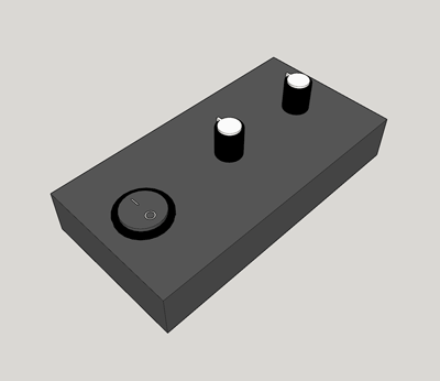
Though I had built boxes for numerous other projects in the past, this was my first experience with SketchUp. I found it easy to learn and quite capable for prototyping. If you are just starting, I recommend watching the official tutorial videos. In particular, it is useful to learn about groups and components, which enable you to operate on multiple objects much more efficiently.
Box Sizing
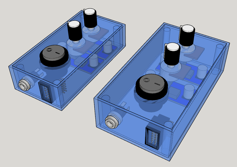
I needed to select a box with sufficient internal space for the two LM2596 power supply boards and enough surface area for several connectors and switches:
- 2x Potentiometer knobs
- On/off switch
- Input barrel jack
- Output header pins
After surveying the available options on DigiKey, I spent some time looking at drawings and testing fit in SketchUp. Since only minimal space would be needed for wiring, I settled on a smaller box.
Panel Cutouts
To cut openings for the potentiometer knobs, switch, and barrel jack, I used a power drill followed by a Dremel grinding stone. Circular cutouts are much easier to make than other shapes, so I tend to keep that in mind when selecting parts.
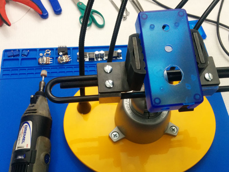
The rectangular opening for the output header pin connector was the most tedious to make. After masking the exposed faces with tape, I used a Dremel cutoff wheel to slowly and carefully cut in from the open edge. Operating the tool at a low RPM helps to avoid melting the plastic, but the cutting wheel still tends to jump. I had to be extra careful since this connector sits flush with the cut edges of the box, meaning there is no overlap to hide imperfections.
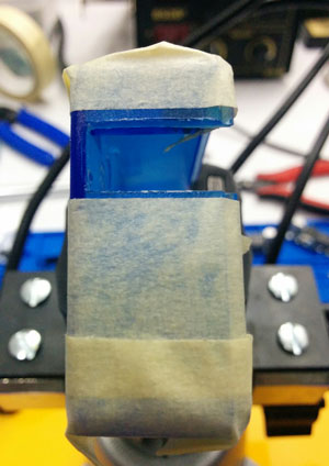
In this case the result turned out well. Some cleanup with a sharp knife helped to remove the few small bits of plastic remaining.
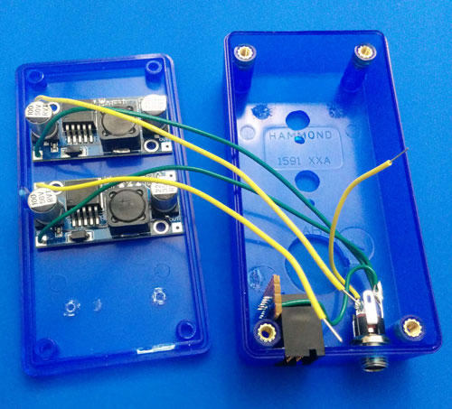
Final Assembly
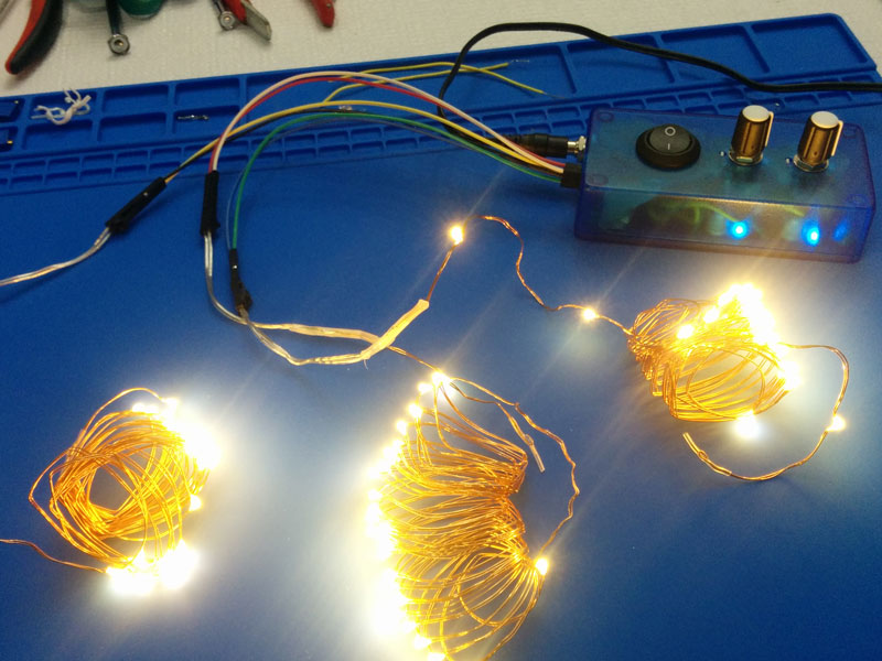
With the panel cutouts finished, I began mounting components and making the required electrical connections. Aside from swapping out the potentiometers and feedback resistors to get the desired output voltage range, the electrical work consisted of simply connecting power and ground. Everything was secured in place with hot glue before closing the box.
With the build finished, it was time to plug in power and dim some LED lights. I was highly satisfied with the results.