Adjustable Power Supply Design
This is a power supply I designed to dim a few strands of inexpensive LED lights. Typically these lights are powered in one of two ways:
- CR2032 batteries, which last only several hours due to their low capacity
- AA batteries, which have higher capacity but drop from 1.5V to about 1.0V as they discharge, causing the LED brightness to vary significantly
With an AC-powered adjustable power supply, there are no batteries to worry about, and the brightness may be set precisely as desired.
| Requirements | |
|---|---|
| Input Voltage | 6-12V |
| Output Voltage | 1.8-3.2V |
| Output Current | 500mA |
Component Selection
The constraints made a linear regulator infeasible due to excessive power dissipation. At maximum input voltage, minimum output voltage, and maximum output current, a linear regulator would dissipate 10.2V * 500mA = 5.1W.
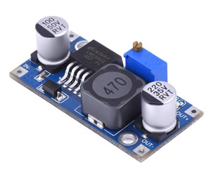
To save time and cost, I selected a preassembled board based on the LM2596 switching regulator. This board is essentially a commodity, available from numerous suppliers for $2 in small quantities.
Modifications
As provided, the board outputs 1.5-35V, adjustable via a multi-turn potentiometer. I wanted to reduce this range so that I could use an external single-turn potentiometer to adjust the output smoothly from 1.8V to 3.2V and prevent overdriving the LEDs. This required a bit of reverse engineering.
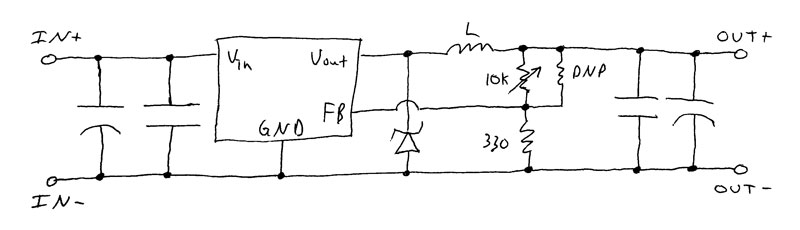
Fortunately, deciphering the schematic from the layout was straightforward. The circuit is a minimal switching regulator design, basically copied from the datasheet. The DNP resistor is an unpopulated 0603 pad underneath the 10k potentiometer.
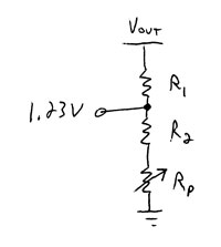
When the LM2596 is properly regulating, the feedback pin is driven through the feedback voltage divider to 1.23V. Thus the output voltage is given by
V_out = (1 + R_top / R_bottom) * 1.23V
The problem with this topology is that potentiometers sometimes briefly open circuit when adjusted. With the potentiometer at the top of the voltage divider, an open circuit would drive the output voltage up to the input voltage, likely damaging whatever is connected. To avoid this, I swapped the locations of the potentiometer and the fixed resistor so that an open circuit will drive the output voltage to its minimum value. A resistor was also added in series with the potentiometer to permit minimum output voltages above 1.23V.
Finally, assuming a 0-1k potentiometer, I calculated values for the two fixed feedback resistors by applying the voltage divider equation to the cases of maximum and minimum output voltage (corresponding to minimum and maximum potentiometer settings, respectively).
V_out(min) = 1.8V = (1 + R1 / (R2 + 1k)) * 1.23V
V_out(max) = 3.2V = (1 + R1 / R2) * 1.23V
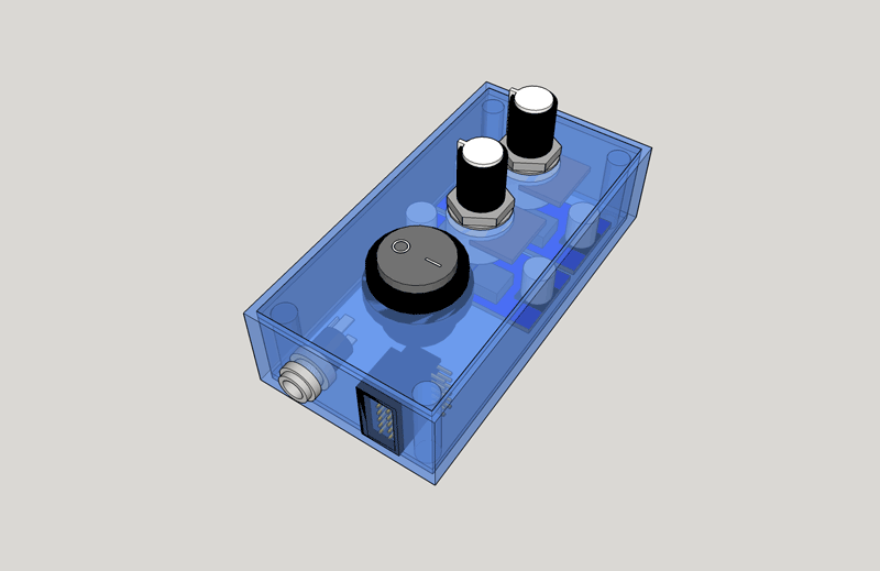
At that point it was time to package the electronics into an enclosure, which I wrote about in a separate post.